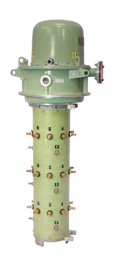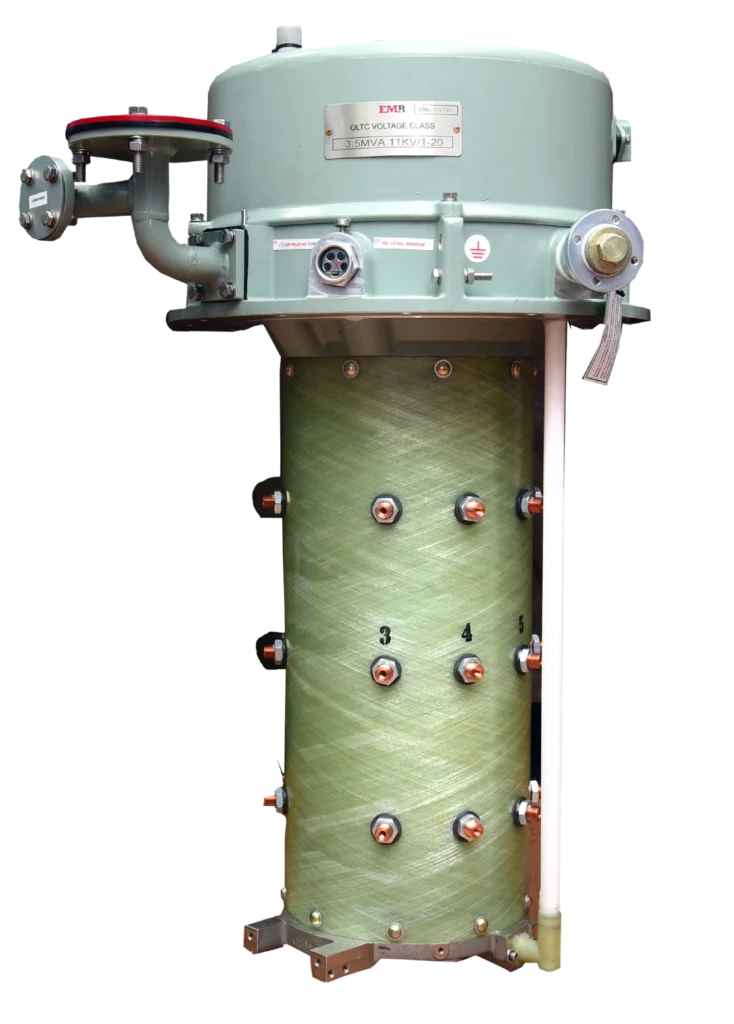
Grid voltage is never perfectly stable. Load switching, lightning strikes, faults on adjacent feeders, and fluctuating renewable generation can all send voltage spikes through the network, and every time this happens, the transformer at the receiving end absorbs the impact first. Left uncontrolled, repeated voltage spikes accelerate insulation ageing, stress the winding, overheat the core, and shorten the operating life of an asset that is meant to last 25+ years.
This is exactly the problem the OLTC (On-Load Tap-Changer) was engineered to address. Unlike a fixed-ratio transformer, an OLTC-equipped transformer can change its turns ratio while still carrying full load current, stepping the output voltage up or down in small increments to counter voltage fluctuations in real time , without interrupting supply. Below is a detailed, technical, 6-step breakdown of how an OLTC actually brings a voltage spike back under control.
Why Voltage Spikes Are a Real Problem for Transformers
Before the 6 steps, it helps to understand what’s actually at risk:
- Insulation stress: Every spike above the rated voltage pushes the winding insulation closer to its breakdown threshold, and cumulative stress shortens transformer life even if no single event causes immediate failure.
- Overexcitation of the core: Voltage rises drive the magnetic core toward saturation, increasing core losses, heating, and noise.
- Downstream equipment risk: Motors, drives, and sensitive electronic loads connected on the secondary side are exposed to the same voltage excursions.
- Unplanned outages: Left unmanaged, repeated spikes eventually trip protection devices or cause premature transformer failure, both of which mean unplanned downtime.
An OLTC directly addresses the root cause , voltage deviation at the source , rather than only protecting against its symptoms.
How OLTC Controls Voltage Spikes: 6 Technical Steps
Step 1: Continuous Voltage Monitoring
The process starts before any spike even occurs. A voltage-sensing relay or Automatic Voltage Regulator (AVR) relay continuously monitors the transformer’s secondary voltage against a pre-set reference band (typically with a defined bandwidth and time delay to avoid reacting to momentary noise). The moment the measured voltage moves outside this tolerance band , due to a spike, sag, or sustained deviation , the relay registers a correction requirement.
Step 2: Command Generation to the Motor Drive Unit
Once a genuine, sustained deviation is confirmed (after the relay’s built-in time delay to filter out transient noise), a tap-change command is sent to the OLTC’s Motor Drive Unit. This is the electromechanical control cabinet that converts the electrical command into a precise mechanical tap-change operation, and it includes the control circuitry, position indication, and interlocks that ensure the change happens safely and in the correct direction , raise or lower.
Step 3: Selector Switch Pre-Selection
Inside the tap-changer, the selector switch mechanism pre-selects the next tap position on the winding before any current is transferred. This selection happens off-load, meaning the new tap contact is prepared mechanically while the transformer continues supplying uninterrupted power through the currently active tap.
Step 4: On-Load Transfer via the Diverter Switch
This is the core of what makes an OLTC different from a simple tap-changer. The diverter switch, using transition resistors (or, in vacuum-type OLTCs, vacuum interrupters), transfers the load current from the old tap to the newly selected tap without breaking the circuit. For a brief transition period, both taps are effectively bridged through the resistors, which limits circulating current and prevents any interruption or arc-related damage during the switch.
Step 5: Step-Wise Voltage Correction
The tap change alters the effective turns ratio of the transformer by one discrete step, nudging the secondary voltage back toward the target band. Because voltage spikes and sustained deviations can be large, the OLTC may execute several sequential single-tap steps , rather than one large jump , to bring the voltage back into range smoothly and safely, avoiding sudden shocks to connected loads.
Step 6: Position Feedback and Continuous Re-Monitoring
After each tap operation, the tap-changer sends a position-feedback signal back to the control and monitoring system (often integrated with SCADA via protocols such as IEC 60870-5-104 or IEC 61850). The voltage relay then re-checks the corrected output against the reference band. If the voltage is still outside tolerance, the cycle repeats from Step 1; if it is within range, the OLTC holds position until the next deviation is detected.
This closed-loop cycle, monitor, command, select, transfer, correct, verify , is what allows an OLTC to keep transformer output voltage stable through continuous grid fluctuations, all while the transformer remains fully energised and on load.
Why This Matters for Transformer Longevity
An OLTC that reacts correctly and quickly to voltage spikes does more than just protect connected loads , it directly protects the transformer’s own insulation, core, and winding from cumulative electrical stress. This is why OLTC selection, motor drive unit quality, and tap-changer maintenance (including periodic oil filtration and contact-condition testing) are treated as core reliability decisions by utilities and industrial power users, not just as a specification checkbox.
EMR Global manufactures OLTC and DETC (De-Energised Tap Changer) solutions for both power and distribution transformers, along with the Motor Drive Units that control them, engineered from decades of tap-changer manufacturing experience to deliver consistent, reliable voltage correction across the transformer’s operating life.
Frequently Asked Questions
What causes voltage spikes in a transformer? Voltage spikes are typically caused by lightning strikes, switching operations on the grid, sudden load changes, faults on nearby feeders, or fluctuations from intermittent generation sources such as solar and wind feeding into the network.
How does an OLTC control voltage without interrupting power supply? An OLTC uses a selector switch to pre-select the next tap position off-load, then a diverter switch transfers current to that tap using transition resistors or vacuum interrupters, so the load circuit is never actually broken during the change.
What is the difference between OLTC and DETC? An OLTC (On-Load Tap-Changer) can change tap positions while the transformer is energised and carrying load, whereas a DETC (De-Energised Tap Changer) can only be adjusted after the transformer is switched off, making it suitable for infrequent, planned ratio adjustments rather than real-time voltage correction.
Can an OLTC respond to a sudden, large voltage spike in one step? An OLTC generally corrects voltage through single, discrete tap steps rather than one large jump, and it may execute a sequence of steps in quick succession to bring a large deviation back within the target voltage band without shocking connected equipment.
What role does the Motor Drive Unit play in OLTC voltage regulation? The Motor Drive Unit is the electromechanical control cabinet that receives the tap-change command from the voltage relay and executes the mechanical tap change safely, including position indication, interlocking, and control logic that governs the direction and timing of every tap movement.