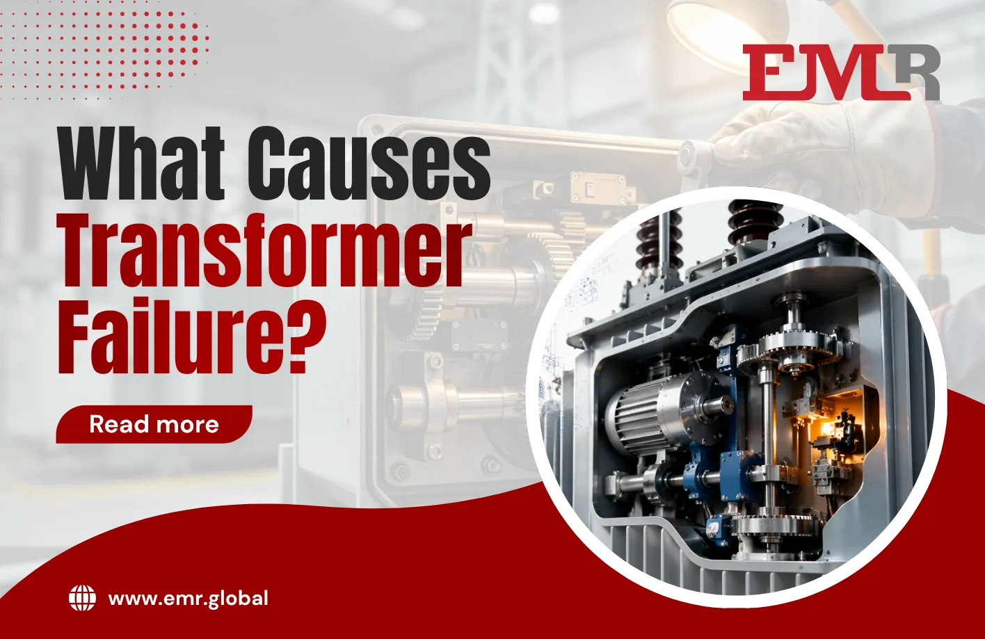
OLTC power transformers rarely fail because of the core, the windings, or the oil. They fail because of a small, often-overlooked mechanical assembly tucked inside the tap-changer compartment: the motor drive unit. If you ask a room full of transformer engineers to name the single component responsible for the most unplanned outages across the global grid, the answer converges again and again on the OLTC motor drive. It’s the part that turns electrical commands into physical motion, and when it stumbles, the entire transformer stumbles with it.
This blog breaks down exactly why the motor drive unit carries so much weight in transformer reliability, how its failure modes cascade into full transformer outages, and what asset owners can actually do about it before a routine tap change turns into an emergency.
Why Transformer Failure Is Rarely About the Transformer Itself
It’s tempting to think of transformer failure in terms of the “big” components — the core steel, the copper windings, the insulation paper, the bushings. These are the parts that get the most attention in design reviews and the most column inches in engineering textbooks. But field failure data tells a different story. Across utilities and industrial fleets worldwide, the On-Load Tap Changer is consistently identified as one of the leading causes of forced transformer outages — and within the OLTC itself, the motor drive unit is disproportionately responsible.
The reason is mechanical, not electrical. Most of a power transformer sits in a sealed, oil-immersed environment with no moving parts and minimal wear. The OLTC is the exception. It’s the only assembly inside the tank designed to move — repeatedly, precisely, and under load — for the entire operating life of the transformer. And the motor drive unit is what makes that movement happen.
What the OLTC Motor Drive Unit Actually Does
The motor drive unit is the mechanical actuator that translates a control signal — whether from an automatic voltage regulator, a SCADA command, or manual operator input — into the physical rotation needed to move the tap-changer’s selector and diverter switch to a new position. It typically consists of a motor, a gear reduction system, limit switches, a torque-limiting clutch, position indicators, and often a hand-crank for manual operation during maintenance.
Every single tap change — and a busy transformer can execute thousands of tap operations per year — depends on this unit performing a precise sequence of steps correctly. Any deviation, even a fraction of a second of timing drift or a slightly worn gear tooth, can leave the tap-changer stalled between positions, misaligned, or in the worst case, mechanically jammed mid-operation.
How Motor Drive Failures Cascade Into Full Transformer Failure
Understanding transformer failure requires understanding how a small mechanical fault becomes a system-wide event. Here’s the typical failure chain:
1. Gradual Mechanical Wear
Gears, bearings, and clutch components wear down over years of repeated operation. This is normal and expected — but without scheduled maintenance, wear accumulates past tolerances that the system was designed to handle.
2. Torque and Timing Deviation
As components wear, the motor drive begins requiring more torque to complete the same tap-change sequence, or takes longer to reach the commanded position. Torque-limiting clutches — designed as a safety feature to prevent damage — can begin slipping prematurely, which stops the switching sequence partway through.
3. Incomplete Tap-Change Operation
This is the critical failure point. If the motor drive stalls mid-sequence, the diverter switch inside the OLTC can be left in an intermediate position — neither fully on the old tap nor the new one. This condition creates abnormal contact resistance and localized heating inside the OLTC compartment.
4. Thermal and Dielectric Breakdown
Sustained heating from a stalled or misaligned switch accelerates oil degradation in the diverter switch compartment. Left undetected, this leads to arcing, oil carbonization, and eventually a dielectric breakdown — the point at which what started as a mechanical hiccup becomes an electrical fault.
5. Forced Outage or Catastrophic Failure
Depending on how quickly the fault is detected, the outcome ranges from a controlled forced outage (the transformer is taken offline for inspection) to a catastrophic failure involving internal arcing, gas generation, and — in the worst documented cases — transformer fires or explosions.
This chain illustrates why motor drive maintenance isn’t a minor housekeeping item. It’s directly upstream of some of the most severe failure modes a power transformer can experience.
The Warning Signs Most Fleets Miss
Because the motor drive unit is mechanical and largely invisible during normal operation, its degradation often goes unnoticed until it’s already causing electrical symptoms. The warning signs that predictive maintenance programs should be watching for include:
- Increasing operation time for a tap-change cycle compared to baseline commissioning data
- Rising motor current draw during switching, indicating increased mechanical resistance
- Position indicator mismatches between the local mechanical counter and the remote SCADA reading
- Unusual vibration or noise during operation, often picked up by acoustic or vibration sensors
- Dissolved gas analysis (DGA) anomalies in the diverter switch oil, particularly elevated ethylene or acetylene, which point to thermal or arcing events already in progress
Modern condition-monitoring systems can track motor torque and timing data operation-by-operation, building a trend line that flags gradual degradation long before a stall event occurs. Fleets that have adopted this kind of monitoring consistently report catching motor drive issues during scheduled maintenance windows rather than during forced outages.
Preventing Transformer Failure Through Motor Drive Maintenance
The good news is that motor drive-related transformer failure is one of the more preventable categories of failure in the entire fleet, provided maintenance keeps pace with the unit’s actual operating cycles rather than a fixed calendar schedule. A practical maintenance approach includes:
- Operation-count-based servicing rather than purely time-based intervals, since a heavily used transformer will wear its motor drive faster than a lightly loaded one on the same age schedule.
- Torque and timing baseline logging at commissioning, so future readings have something meaningful to compare against.
- Periodic manual operation checks, verifying the hand-crank and mechanical position indicators agree with the electrical position signal.
- Lubrication and gear inspection on the schedule specified by the original manufacturer, adjusted for actual duty cycle in high-switching applications like renewable integration points or industrial load-balancing transformers.
- Contingency sourcing plans for replacement motor drive assemblies and OLTC components, so that when a unit does show signs of failure, a compatible replacement isn’t a months-long wait.
That last point matters more than it might seem. Motor drive units are specific to the OLTC brand and model, and for older or discontinued tap-changer designs, sourcing a compatible replacement quickly can be the difference between a planned maintenance swap and an extended forced outage. This is precisely the kind of situation where working with a global sourcing partner familiar with OLTC power transformers across multiple brands — including legacy designs — pays for itself many times over.
Bringing It Back to the Bigger Picture
Transformer failure investigations often start by looking at the biggest, most expensive components first. But the data consistently points to a smaller truth: the parts most likely to fail are the parts most likely to move. The OLTC motor drive unit sits at exactly that intersection — mechanical, repetitive, and absolutely essential to safe voltage regulation.
Understanding this doesn’t just help with root-cause analysis after a failure. It reshapes how maintenance budgets, monitoring investments, and spare parts strategies should be prioritized in the first place. For any organization managing a fleet of OLTC power transformers, the motor drive unit deserves the same level of attention as the core and windings — because in practice, it’s often the component writing the first chapter of the failure story.
Final Thoughts
The next time a transformer failure investigation begins, it’s worth starting the search not at the core or the bushings, but at the small motor assembly quietly executing thousands of tap changes a year. Catching wear early, monitoring torque and timing trends, and having a reliable path to source replacement components are the three pillars that keep an unplanned outage from ever happening in the first place.